In automated facilities, the ability to start, stop, and redirect airflow with precision is what separates a smoothly running production line from one that loses time to inconsistency and unplanned downtime. Pneumatic valves make this control possible. Embedded across conveyors, assembly stations, mixing systems, and safety circuits, they direct compressed air to actuators, cylinders, and tools at exactly the right moment. For maintenance engineers and plant managers evaluating their pneumatic systems, understanding how different valve types function and what drives selection decisions is the foundation of reliable industrial automation.
What Pneumatic Valves Do and How They Work
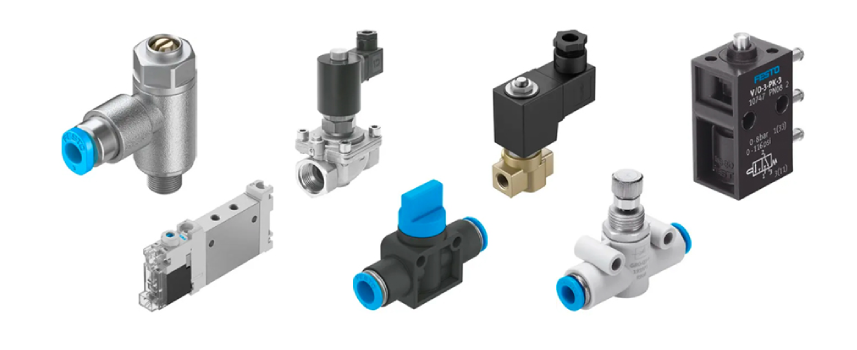
Pneumatic valves play a central role in controlling the flow of compressed air within an automated system. When a signal is received, whether electrical, mechanical, or pneumatic, the valve opens, closes, or shifts position to route air through the intended pathway. This converts air pressure into mechanical motion across the system.
Air supply pressure, typically delivered between 4 and 10 bar in industrial pneumatic systems, determines how much power is available to perform work at the actuator. The valve regulates how that air is directed, at what rate, and in which direction, making it the primary control component between the compressor and the working parts of the machine.
Solenoid valves use an electromagnetic coil that is energised by an electrical signal to shift the valve mechanism, allowing direct integration with PLCs and control systems. Pilot operated valves use a smaller pneumatic signal delivered through a pilot valve to shift a larger valve body, which suits high-pressure or high-flow circuits where direct solenoid force is insufficient. Manual actuation via levers or push buttons remains relevant in maintenance, testing, and emergency override scenarios.
Types of Pneumatic Valves in Industrial Automation: Solenoid Valves and Pilot Valves
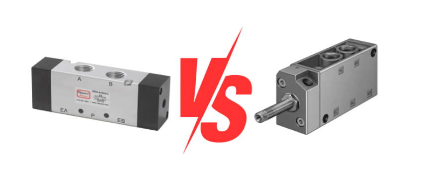
The two main types of pneumatic valves used in industrial automation are solenoid valves and air pilot valves. Each operates differently and suits different application conditions.
Solenoid valves are operated by an electrical signal. When the coil is energised, it generates a magnetic force that shifts the spool inside the valve body. This spool movement controls which ports are open or blocked, determining the direction of air flow through the valve. A simple two-port solenoid valve performs basic on/off control, either allowing air through one port or blocking it completely. More commonly in automation, a 5/2 solenoid valve has five ports and two positions. In practice, this means it can direct compressed air to either side of a double acting cylinder, pushing the piston in one direction while exhausting air from the opposite side. A 5/3 valve adds a third neutral centre position, which allows the cylinder to be held in place, fully exhausted, or pressurised on both sides depending on the system requirement.
Spring return solenoid valves use a mechanical spring to push the spool back to its default position the moment the coil is de-energised. This is useful in safety-critical applications because the valve automatically returns to a known safe state if electrical power is lost. Double solenoid valves, by contrast, use two coils and hold their last position when power is removed, which suits applications where the actuator must stay in place during a power interruption.
Quick exhaust valves are a common addition to solenoid-controlled circuits in high-speed applications. Rather than routing exhaust air back through the main valve and supply lines, a quick exhaust valve vents air directly to atmosphere from a port close to the cylinder. This reduces back pressure on the piston return stroke and increases cycle speed, which matters in applications like stamping, labelling, and cutting equipment where every fraction of a second affects throughput.
Air pilot valves use compressed air rather than electricity to actuate the valve. A small pilot valve directs a pneumatic signal to shift a larger valve body, making this type well suited to high-pressure or high-flow circuits, as well as hazardous environments where electrical signals are not practical, such as areas with flammable atmospheres. One of the key advantages of air pilot valves is their ability to provide proportional control. Rather than simply switching between on and off, they accept an analogue input signal and adjust the valve opening continuously, giving operators precise control over actuator speed and force. This makes them a good fit for mixing systems, welding positioners, and dispensing equipment where repeatable, fine-tuned motion is required.
Air pilot valves are also used in safety applications. Soft-start valves, for example, use a pilot-controlled mechanism to gradually build air supply pressure when a system is powered on. This prevents sudden shock loads on cylinders and reduces the risk of uncontrolled piston movement at startup. Pressure relief valves open automatically when pressure in the circuit exceeds a set threshold, protecting downstream components from over-pressurisation. In facilities with functional safety requirements, these components are commonly certified to relevant machinery safety standards.
Spring return configurations are available in both solenoid and air pilot valves, returning the valve to a defined safe position when the actuating signal is removed. For a detailed comparison of both valve types including their advantages and limitations, refer to the SLS Bearings guide:
Understanding Pneumatic Valves: Solenoid vs Air Pilot.
Where Pneumatic Valves Are Applied in Industrial Automation
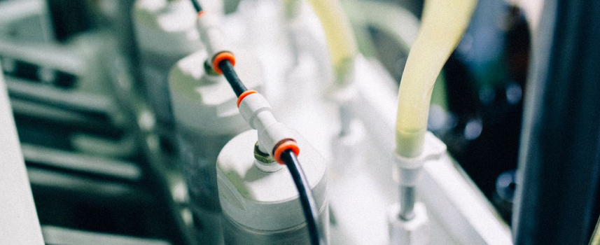
Packaging equipment relies on pneumatic valves at nearly every station. Forming, filling, and sealing machines use solenoid valves to drive jaw actuators, reject gates, and conveyor stops in precise timed sequences. The cycle speeds involved, often hundreds of strokes per minute, demand valves with low response times and consistent switching characteristics across millions of operations.
Assembly lines in automotive and
electronics manufacturing use pneumatic valves to control screwdrivers, presses, clamps, and insertion tools. The integration between valve response and sensor feedback is critical here. A difference in response time of even a few milliseconds can affect cycle time and part quality when the process window is narrow.
Material handling systems, including pneumatic conveying lines, diverter gates, and sortation equipment, use control valves to manage air flow to transfer points and routing mechanisms. In food and beverage processing, valve construction and cleaning compatibility must also meet hygiene standards, making material selection an additional consideration.
In the
food and beverage industry, mixing and blending systems rely on pneumatic valves to control the opening and closing of ingredient feed lines. The repeatability of each valve operation directly affects batch consistency, making calibration and response time important factors in valve selection for these processes.
Safety shutdown systems use dedicated spring return or fail-safe valves that return to a closed or exhaust position on loss of power or signal, isolating energy sources and placing equipment in a safe state. These components are specified for both performance and compliance with machinery safety standards.
Key Selection Criteria for Pneumatic Control Valves
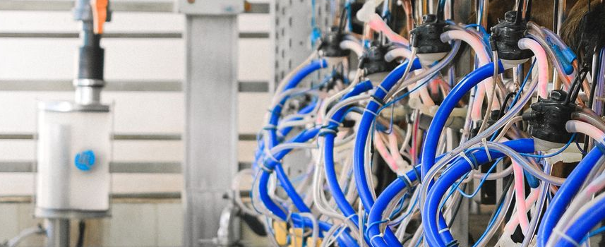
Flow rate capacity, expressed as a flow coefficient (Cv) or nominal flow value, must match the demands being supplied. An undersized valve restricts air flow and slows motion, while an oversized valve may respond inconsistently in low-flow applications. Calculating the required flow based on cylinder bore, stroke length, and desired cycle time provides the starting point for valve sizing.
Response time refers to the interval between the control signal and full valve actuation. For solenoid operated valves, this is influenced by coil design, supply voltage, and air pressure at the inlet. Response times typically range from a few milliseconds to around 50 milliseconds and should always be confirmed from manufacturer data for high-speed applications.
Pressure rating defines the maximum operating pressure the valve can handle reliably across its service life. Most industrial pneumatic systems operate between 4 and 10 bar, but circuits with intensified pressure require valves rated with an appropriate safety margin. Minimum operating pressure is equally important, as some valves may not function correctly at the lower end of their rated range.
Environmental protection ratings, indicated by IP codes, determine suitability for the installation environment. Temperature range, dust exposure, and contact with fluids or cleaning agents all influence which valve types are appropriate for a given installation.
Material compatibility applies to seals and internal components in contact with the air supply or process fluids. Standard NBR seals suit most compressed air applications, but oil-free systems, specific lubricants, or food contact zones require seal material and body construction to be confirmed. Stainless steel body valves are available for hygienic and corrosive environments, and friction characteristics of seal materials affect both response consistency and service life.
Selecting the Right Pneumatic Valve for Your Process
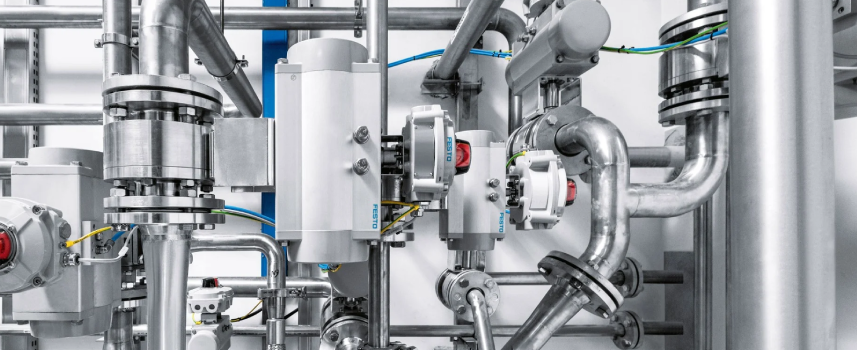
The selection process begins with a clear picture of the application: the actuator or circuit the valve serves, cycle rate, operating pressure and flow range, control interface, and installation environment. These parameters define the performance class that applies.
Matching valve type to function ensures the chosen component is designed for the task at hand. Reviewing manufacturer data for Cv ratings, response times, seal compatibility, and applicable safety certifications rounds out the verification before installation.
SLS Bearings supplies pneumatic valves suited to industrial automation applications. To explore available valve types and specifications for your system, visit our
Pneumatic Valves and Valve Terminals page.
Conclusion
Pneumatic valves are central to how automated processes are controlled, sequenced, and protected. Whether directing cylinder strokes in a packaging line, modulating force in an assembly press, or isolating energy in a safety shutdown, each valve type serves a distinct engineering function. Selecting the right valve means matching flow rate, air pressure requirements, response time, environmental suitability, and material compatibility to the demands of the application.
If you need guidance on pneumatic valve selection for your facility,
contact us at SLS Bearings. Our team can help identify the right valve for your process requirements.

 sg
sg


 Contact Us